ACE PRO “Dual stack” with slide out lower tray


ACE Dual Stack
Stack 2 ACE pro units on top each other while allowing the bottom ACE to be pulled out to manage the filament.
I printed everything on a K3C in PLA.
My settings were; 0.2mm layer height. Infill = 15%. Wall Loops = 4. infill pattern = 3D Honeycomb.
Width of Dual Stack is ~16.5in(42cm), Depth is ~16in(40cm), Height is 20.5in(52cm)
Thats with none of the accessories attached and 15cm standoffs installed to keep it from the wall.
Added V2.
Increased the M3 screw heads to 5.75mm
Reduced the size of the pillars by 0.2mm so they assemble easier.
Added some additional mounting holes on top rails for future parts.
Parts are still compatible.
Took the front rail out of the Support as its got color.
Split the Plates into 3 now.
NEW:
Added assemblies for larger printer builds.
If you have access to a printer bigger than the K3 you can print the 3 biggest parts together.
Note: The single piece ACE slide out tray is here
XRISERS.STL 220x250mm
UPPERACETRAY.STL 415x250mm
BOTACETRAY.STL 415x270mm
Options for support of power or tool box on ends of the stack.
Use the PTFE comb to manage the filament and run the PTFE tubes up and over the top of the printer, not to the left side.
Combs
Toolbox's
Large Toolbox
Small Toolbox
The model requires 34 M3x16 SHCS screws to hold everything together. No glue required.
Affiliate Link: https://amzn.to/40nIDyz
requires 6 pieces of 608ZZ roller bearings or the included printed part may be used but will not roll as well.
Affiliate Link: https://amzn.to/40mlyfA
requires 4 10mmx3mm refrigerator magnets.
Affiliate Link: https://amzn.to/4fJYfkh
Assemble the Tray first, Print Tray.3mf (TrayV2.3mf)
TrayFront, TrayLeft, TrayRight. print either the Plastic Wheels or the bearing bushings if you use bearings BearingBushing, Optional PlasticBearing
Insert the 8mm bushings into the bearings. Insert the bearings into TrayLeftSide and TraySideRight. Use a M3x16 screw to fasten each bearing.
Insert 2 of the magnets in the ends of the tray supports. Glue may be required. Make sure the magnets are installed attracting not opposing.
Once the sides are assembled, attach the Trayfront with handle up to both sides and use 2 M3x16 screws to secure.
Next using 4 M3x16 screws attach the assembly to the bottom of the lower ACE unit. Putting the ACE on its lid helps here.
The ACE unit should now roll on the table freely.
Tray has been moved to here.
Print FrontV2 (front Anycubic logo)
Select your colors. No logo, put logo in the back or stop printing at layer 100.
Assemble the support, Support.3mf (RackV2)
BottomPadM, BottomPadR, XRiser x4, TopSideRight, TopSideLeft, Backbar
Insert 2 of the magnets in the BottomPadM and BottomPadR. May need glue.
Attach The bottomPadM and R to the Backbar. Use M3x16 screws to secure all the parts.
Using the top Sideview picture insert the front XRiser into the bottomPad. Next insert the back XRiser. Makes sure you insert the front one first on both sides.
Use 3 M3x16 screws to secure the XRiser together and to the BottomPads. Repeat on other side.
Attach The TopFront to both the TopSideLeft and TopSideRight. Secure with M3x16 screws.
Attach this assembly onto the top of the XRisers. Make sure the Anycubic logo is towards the front if you want the LOGO, if not point it towards the back.
May require some force to push them down all the way.
Secure with 4 M3x16 screws.
Next using 4 M3x16 screws attach the upper ACE unit.
Optional Back Spacer.
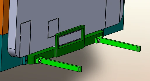 To keep it from getting too close to the wall. Backspacer100mm and ACEBackSpace150mm
I added 100mm and 150mm. Use 2 of whatever works for you. Requires 4 M3x16 screws.
Optional power outlet:
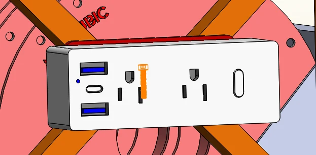
Bolt the PowerStripMount to the new xriser with 4 m3x16 screws. Then place appropriate screws to hang power outlet.
I used #8 Sheet metal Screws. Drywall screws should also work. I provided 2 size holes just in case.
I also provided the STEP file so you can adjust the design to match your power strip.
Affiliate Link: https://amzn.to/40qqWOI
Done:
Slide the ACE on the tray under the supported unit. Connect all your PTFE and ready to print.
i taped the USB cable to the upper back of the lower ACE to keep it out of the way.
Hints:
All these files were printed on a Kobra 3
Pre insert the screws into the bottom of the ACE units to cut a few threads first. Then remove the screws for final assembly.
Set the ACE upside down when trying to attach it to the rest. Place a soft towel down first to avoid scratching the ACE all up.
A small hammer might be needed to pop the inserts together.
I used PLA. Some may prefer PETG or ABS.
Please comment and give a like if you like what you see.
If you see something you think might need modifying then comment and I will see what I can do for you.
You are prohibited from sharing, sub-licensing, selling, renting, hosting, transferring, or distributing the digital file or 3D printed versions of this object, as well as any other derivative work in either digital or physical form (including remixes).You are not allowed to use the objects in any manner that involves charging money or collecting fees without permission.