Kobra S1 Full Bed Test. First Layer Troubleshooting Guide.


If you're having problems with the first layer on your Kobra S1, this test and guide will attempt to help you identify and diagnose the problem.
Let's assume that you've already completed following standard suggestions:
- Wash your build plate with hot water and mild dish soap (like Blue Dawn).
- Not alcohol - alcohol mostly distributes the oil and doesn't fully remove the oil.
- Make sure to use a clean sponge and scrub thoroughly to loosen any oils that are embedded in the plate's texture.
- Make sure your nozzle is clean and free of residual/crusted filament and debris. If not, heat the nozzle up and give it a good scrub with a brass wire brush.
- More specialized measures to make this more consistent including nozzle wiper mods as well as custom firmware mods to try and improve the nozzle wiping performance. This is outside of the scope of this guide.
- Re-run calibration and bed leveling
- With firmware mods you can tweak the printer to perform bed leveling at the same temperature you're printing at. This has potential warranty implications so proceed with caution. I've not tried this so this is an exercise for the user if you want to try this.
I'll start by explaining how to read the first layer test. Then I'll explain the causes I'm aware of, continue to ways to diagnose the specific causes, and the end with the known fixes to address the problems.
Instructions
Use a standard high gloss filament - not a matte filament.
Use a filament color that contrasts well with your build plate. (Don't print black filament on black plate)
Interpreting Results
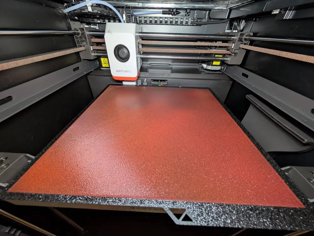
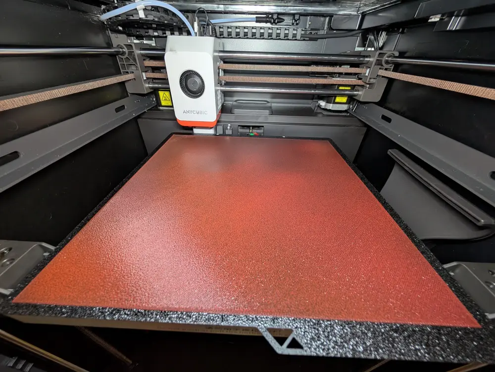
You should see something like this when the print completes. Notice that you can already see bright points of light reflecting off of the build plate texture through gaps in the filament. You'll want to remove the build plate and hold this up in light to inspect it more closely.
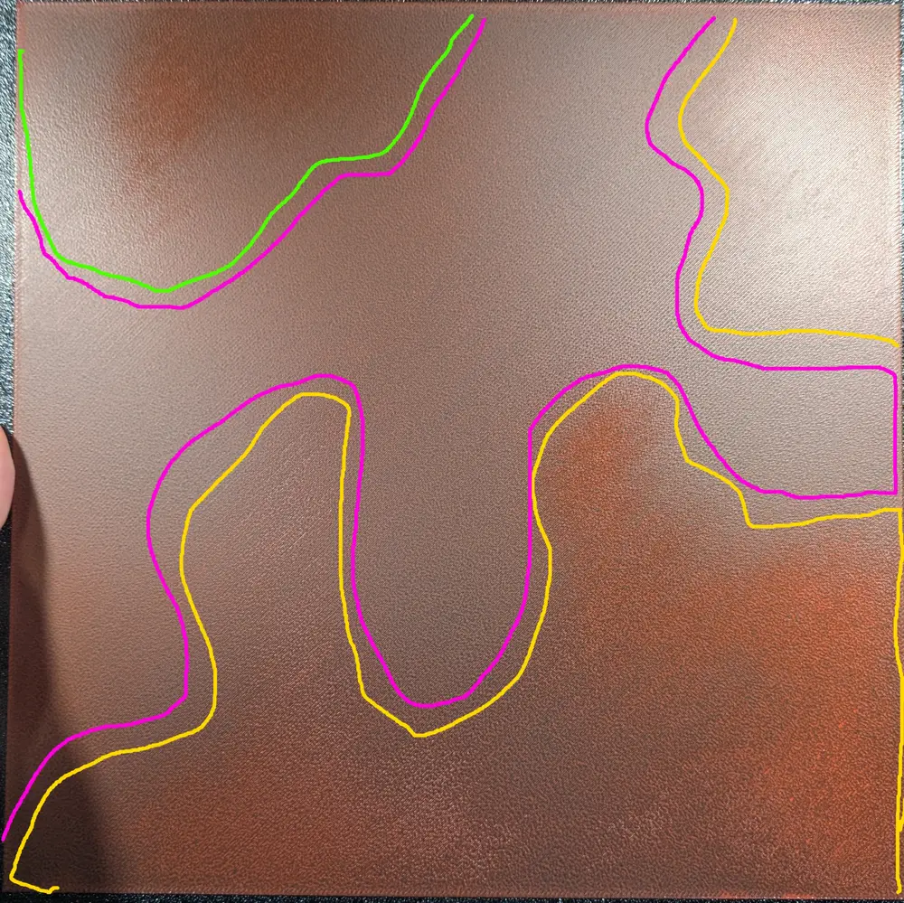
Below is my annotated image with areas that are high or low.
- Yellow - Low points. Visible gaps in the printed lines and the build plate texture reflecting light between the gaps.
- Purple - High points. The plastic's luster is dulled from the nozzle pushing around excess filament. When this is very high (or the Z offset is set too negative) you'll see ripples from the nozzle pulling on the excess filament being squeezed sideways as it is printing.
- Green - Just right. It's a nice flat layer. It has a nice even shine from the plastic with no gaps and you can see a hint of the tiny seam where two printed lines meet.
Issues
There are a few different causes working together to create problems with achieving a first layer
- Z-Offset needs adjusting. The printer does an automatic Z offset adjustment but most people find that it is slightly too high leading to problems.
- The Z-Axis sliding blocks are out of alignment. The Z-Axis sliding blocks are the plastic blocks that rides on the 3 vertical screws. It's not uncommon for these to be slightly out of alignment out of the factory. What this means is the entire bed is now tilted at an odd angle.
- The bed is warped. The aluminum bed on the S1 is only 3mm thick and it is very common for it to become warped when heated up. It's not uncommon for it to arrive warped from the factory.
- The carriage flexes when probed. The heat bed is attached to a metal carriage and the metal carriage is attached to the 3 z-axis sliding blocks. This carriage is pretty thin and flexes pretty easily. The force of the nozzle probing on the bed pushes and flexes the bed and causes bad readings - especially in the back left and back right corners.
Z Offset
Identifying
What you'll see is a fairly consistent result through the entire build plate. The entire plate will have gaps or the entire plate has ripples
Solution
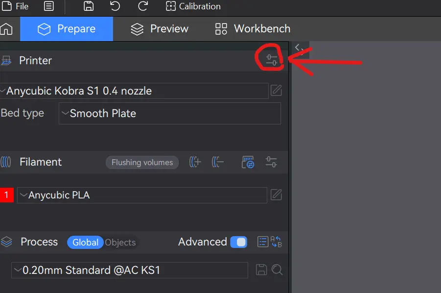
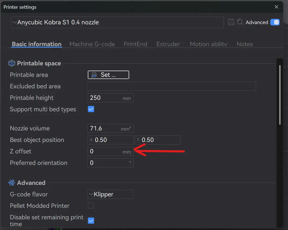
Adjust the Z-offset in printer profile setting in the slicer. (See pictures)
Decreasing the value moves the nozzle closer to the bed. Increasing the value moves the nozzle further from the bed.
I've seen people use values from -0.02 to -0.05mm. For reference, I use -0.03mm.
Z-Axis Sliding Block
Identifying the problem
What you're looking for is whether the entire bed is tilted. With these instructions you're basically using the nozzle as a rough measurement of the distance the bed is from the nozzle.
- First home your Z axis (if not, the printer will make you do it anyway).
- Then move the bed up until it touches the nozzle.
- Turn off the printer
- Now very slowly move the print head forward and back and left and right. Make sure to do this slowly as it will start rubbing against the build plate on the high points.
- Try to approach each Z axis (vertical) screw. You should be able to identify ones that are particularly low or particularly high.
Solutions
There's the 'right' way and there's the 'easy' way. The right way is to tram the bed which involves disengaging the belts from the z axis screws, rotating each screw manually so that it lines up, and then re-attaching the belt. It's labor intensive and it'll take multiple trials to get it right.
'Right' Way -
I've not tried this myself but I found this wiki entry for adjusting the sliding blocks.
Easy 1 - Shim the low axis (or axes)
The easy way is to shim up the axis (or two axes) that are low to match the highest sliding block.
Kanrog Creations designed these simple shims that you can slip in between the carriage plate and each sliding block. You can scale the model vertically up or down to the distance you need for that axis. I recommend printing this in PETG.
Easy 2 - Install Silicone Stand-offs
You can install silicone stand-offs made for other printers on your bed between the bed and the carriage. This lets you raise-lower the bed by loosening or tightening the screw attaching the bed to the carriage.
Warped Bed
Identifying the problem
Your result will look like my example above with regions of high and low points.
Solutions
Replace with stock bed
If you report your warped bed to AnyCubic support and you're still under warranty, they'll usually replace your bed. The easiest way to document this is to use a metal ruler turned on edge on the bed and take a picture of the gaps from the warped bed. Similar to this: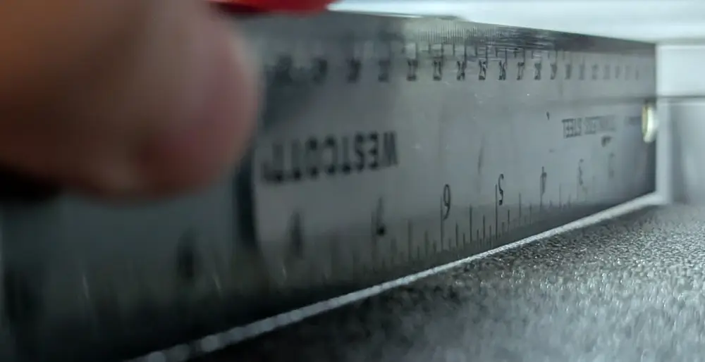
Replace with after-market bed
I have not tried this personally but many people in the community have gone this rout.
There is a seller on Aliexpress that sells an 8mm aluminum heat bed kit. It costs in the neighborhood of US $110.
The 8mm is much more stable and results in a nearly perfectly flat bed.
Tighten with additional screws
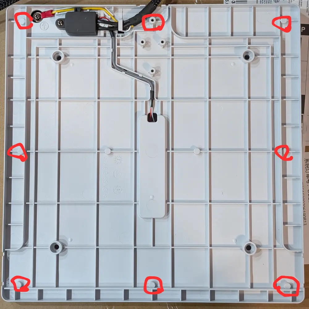
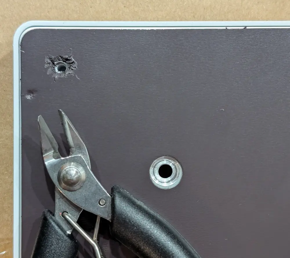
I'll start by saying I tried this and it didn't help me but others reported that it helped them. If you look under the heat bed you'll see these 9 points (circled in red). Above these 9 points, hidden under the magnetic sheet, the aluminum bed has holes drilled but not used. If you cut away a small hole in the magnetic sheet you can expose the holes and screw them into the plastic frame. Be careful as it is plastic and if you over-tighten you'll just strip the plastic.
Requires:
- 8x M3x6mm screws for this. I bought these 10.9 hardened steel screws.
Increase Bed Mesh Points
This is potentially warranty-voiding so proceed at your own risk here. There is community maintained firmware mod project called Rinkhals. If you install Rinkhals you can modify your printer.custom.cfg file to add the following.
These changes increase the mesh to 7x7 but lowers it to 1 sample per point, which results in 49 probes. The stock configuration is a 5x5 mesh with 2 samples per point, or 50 probes. There are also some changes to movement and probing speed. you can omit those if you don't want to increase your probing speed.
[probe]
speed : 10.0 # original 4
final_speed : 10.0 # original 4
lift_speed : 20.0 # original 4
samples: 1 # original 2

[bed_mesh]
speed: 500 # original 300
horizontal_move_z: 2 # original 3
probe_count:7,7  # original 5,5
algorithm:bicubic  # original lagrange
Carriage Flex
Identifying the problem
With this you'll find that issues with your first layer primarily shows up in the back left and back right corners. The community's consensus is that the carriage frame flexes during probing because the back of the bed is supported at a single weak point at the back z axis sliding block.
Solutions
Carriage Sandwich
If you requested a replacement bed from AnyCubic for a warped bed, you'll now have two beds, frames, and carriages. If you take the two carriages and sandwich them together with some printed blocks (Use ABS or ASA), you can create a carriage sandwich that is more rigid and less prone to flexing.
Kanrog Creations has modeled this set of blocks to sandwich between the carriages.
Requires:
- 15x M3x12mm bolts and nuts.
This is on my To-Do list and I'll document when I get around to it.
Replacement After-market Carriage (Aliexpress)
The same seller that makes the 8mm aluminum bed also sells a 5mm solid aluminum carriage. It's about US $70. I haven't gone this route but many people have reported success with this.
Replacement After-market Carriage (Laser Cut)
Kanrog Creations has created this laser-cut model if you have access to the equipment and materials to manufacture your own carriage.
You are prohibited from sharing, sub-licensing, selling, renting, hosting, transferring, or distributing the digital file or 3D printed versions of this object, as well as any other derivative work in either digital or physical form (including remixes).You are not allowed to use the objects in any manner that involves charging money or collecting fees without permission.