Playing cards holder


Below you'll find a guide to quick and easy removal of supports and a full guide how to use parametric Fusion 360 to create a personalized version and a small guide on how to calculate the length of the spring.
As already told on these pages, my wife suffers from a neurological progressive disorder that gives her limitations on things like having a strong grasp on objects. Also my mother suffers from rheumatoid arthritis which causes her pain to the joints of the hands.
We still like to enjoy our evenings while playing card games, so I noticed how tired my wife was after some long sessions, I decided to help them out by downloading a holder for playing cards, but the available ones are basically two disks joint together.
So after a lot of trials and error I finished up with this design which requires a compression spring of 25mm or 30mm of length and gives a good fell at keeping, removing or adding cards to it.
It can also be left on the table without handling it and if you want to hide your cards, you can also have it lying down on the table with faces to the bottom.
Usage policy
If you print this for someone, please DON'T DO IT FOR MONEY. It's unethical. A single holder uses in total less that 20 grams of PLA and takes very less than one hour print time, you can get the springs for 0,20€ or reuse those in old pens, so the cost is ridiculous.
Assembly guide
You will need a 25mm or 30mm spring to keep the two parts together.
To be able to create a holder you will need to:
- print the two parts;
- remove brim;
- remove supports;
- merge the two parts by passing one pin in the hole of the other piece;
- insert the spring in between as shown in this section view.
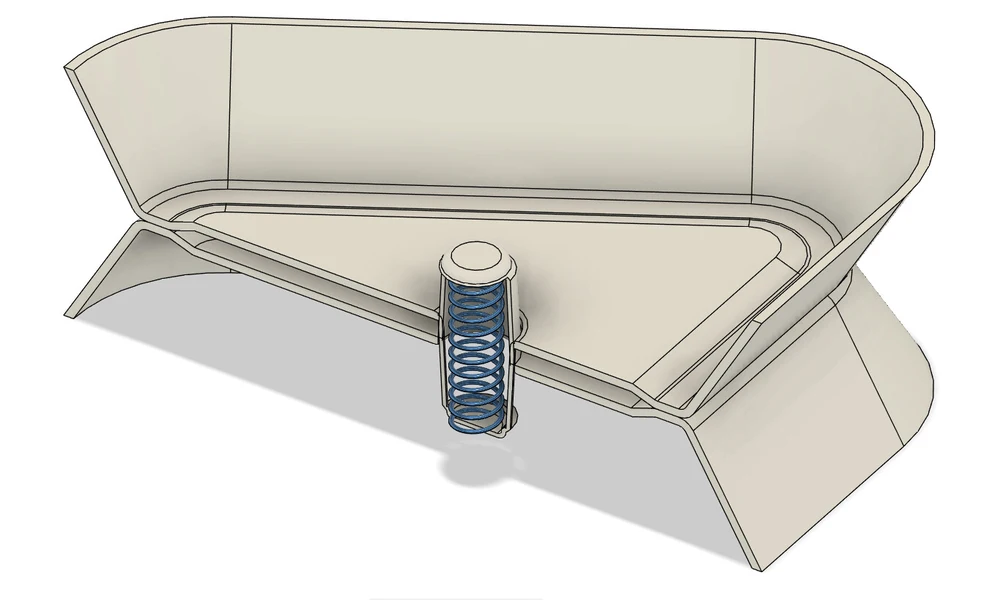
Guide to quick and easy removal of supports
After printing the model a single tree support will be present and attached to what seems to be a delicate part of the design, follow these instructions to easily remove it.
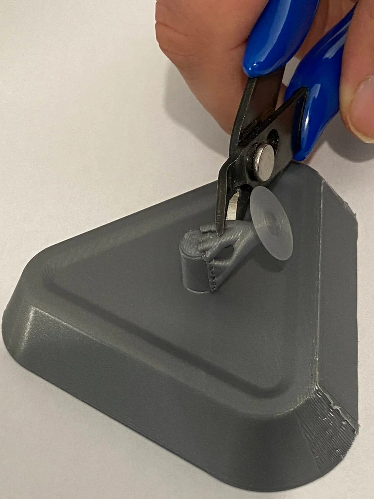
Step 1: cut the upper branches of the tree.
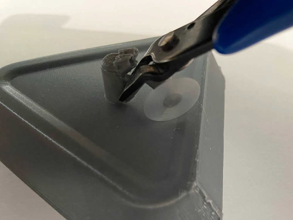
Step 2: by holding the vertical branches of the tree with the wire cutter, gently swing it left and right, the bottom part of the tree will detach and fall apart.
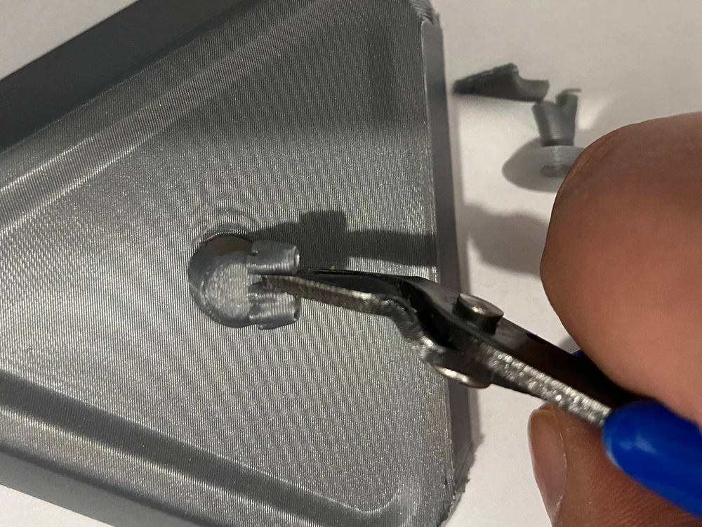
Step 3: cut in between the two major branches and the upper branch will fall apart.
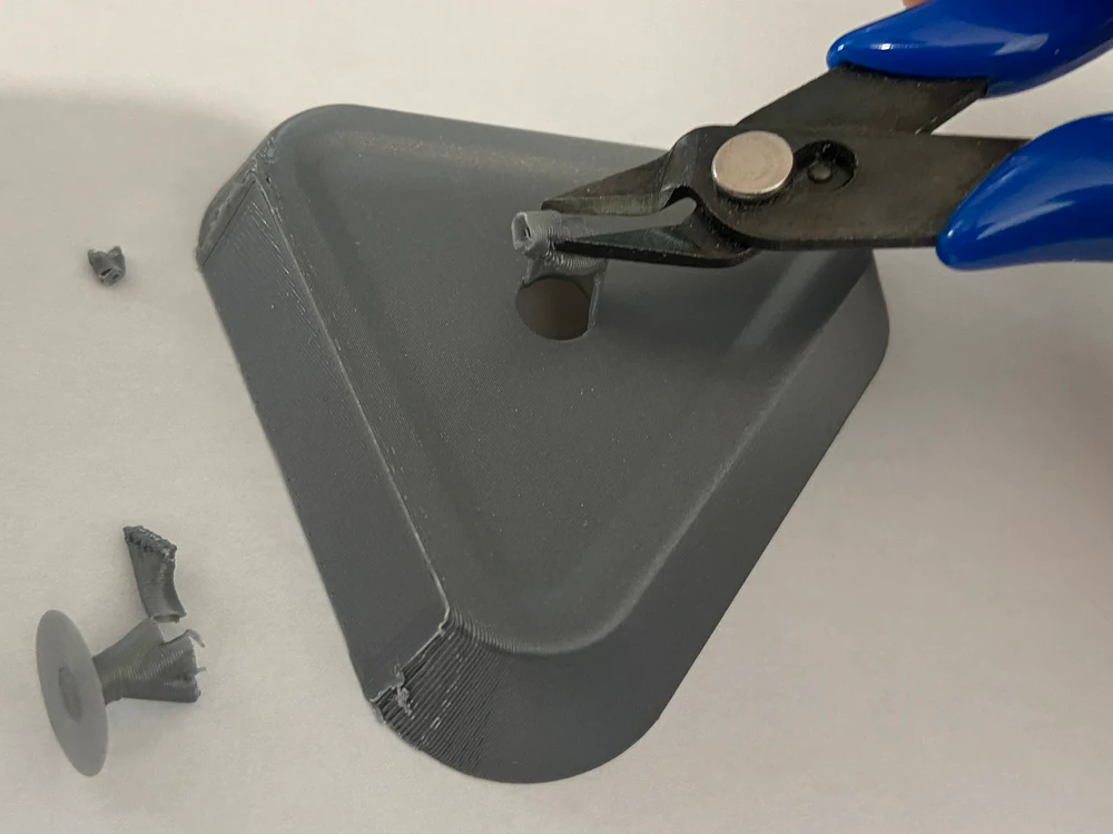
Step 4: lay the cutter horizontally and gently squeeze the cutter, the last part will fall apart.
For better results, use some sandpaper to remove excesses from the bottom corners of the holder.
After doing this for both parts, merge them by passing one pin in the hole of the other piece and then put in place the compression spring.
Personalizing in Fusion 360
I'm providing the source Fusion 360 file that I've created the most parametric I could, so anyone can personalize this design for best fitting their necessity. Once imported in Fusion 360, go into the SOLID toolbar, under MODIFY menu select “Change Parameters” you can change all parameters from this window.
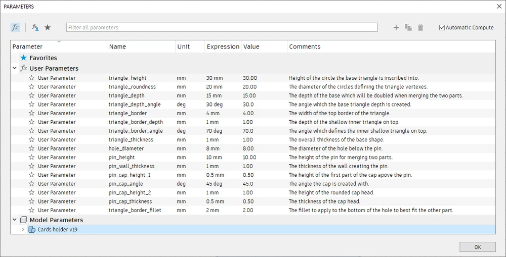
Simple visual explanation of parameters
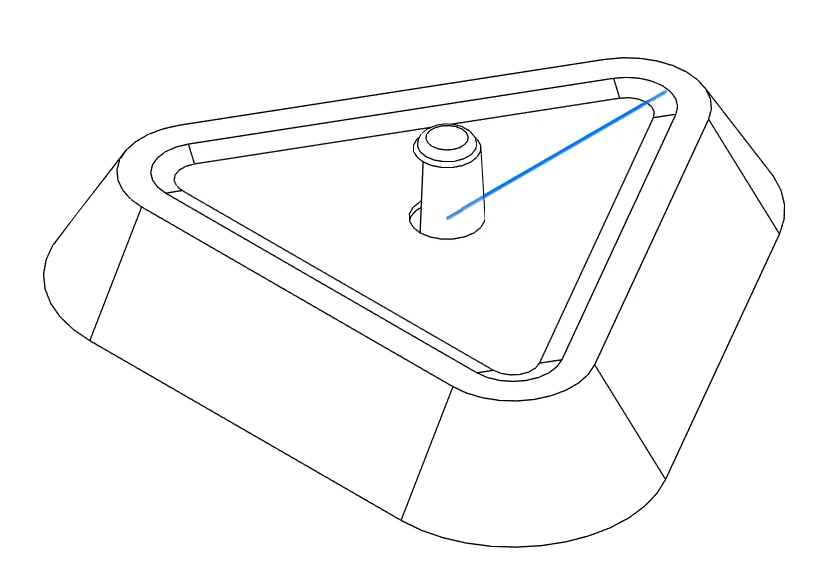
triangle_height: the radius of the circle where the base triangle is inscribed.
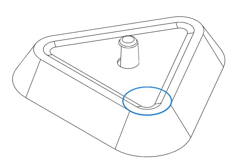
triangle_roundness: the diameter of the circle at each angle of the base triangle that defines the external shape.
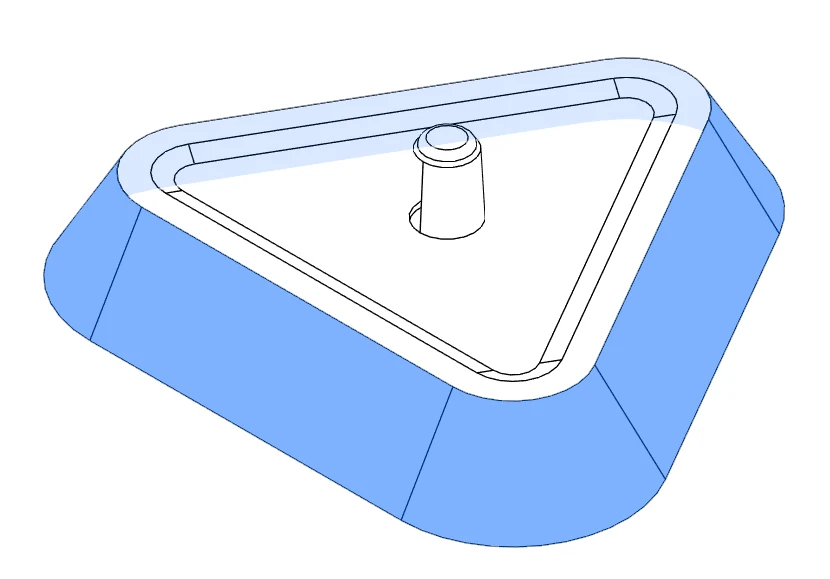
triangle_depth: the height of the half of the holder.
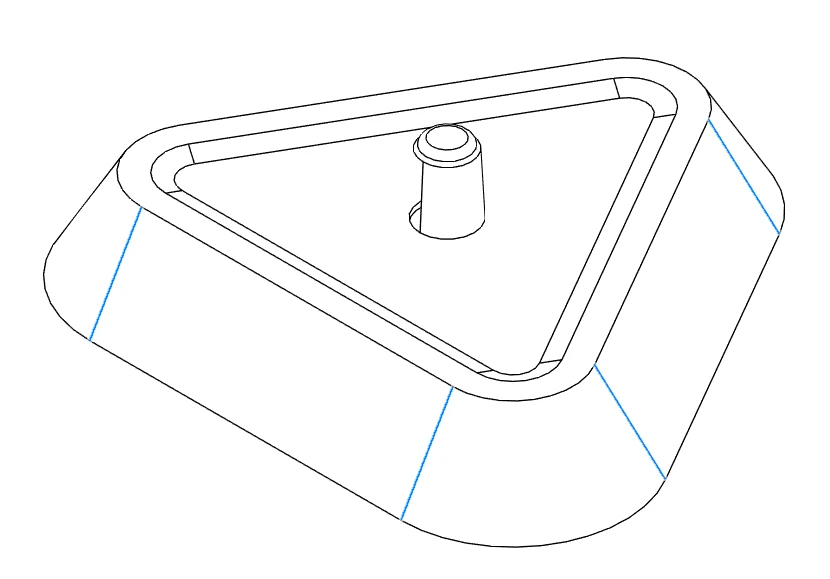
triangle_depth_angle: the angle at which the triangle extends.
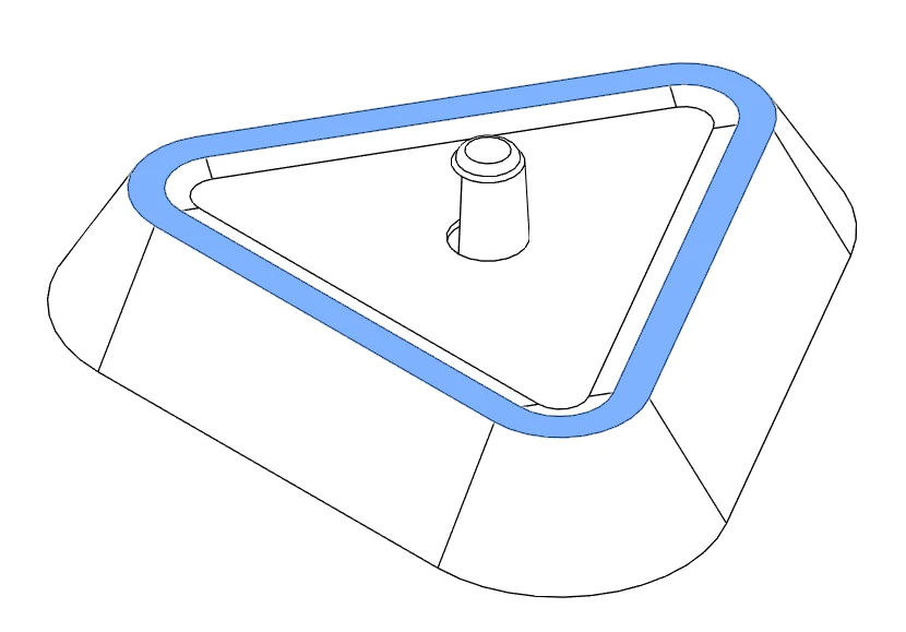
triangle_border: the width of the upper border of the triangle.
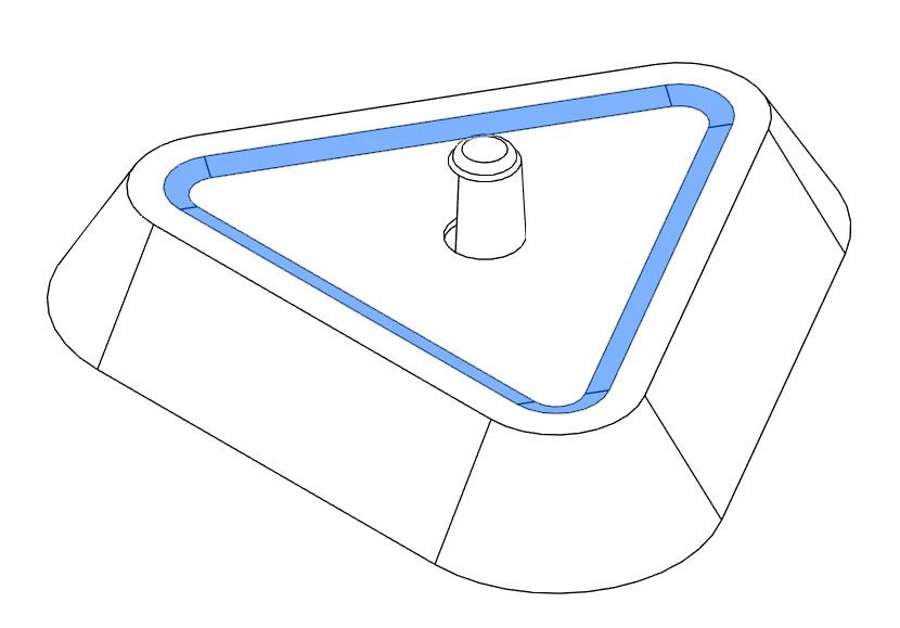
triangle_border_depth: the height to which the upper border extends. This will influence the length of the spring required.
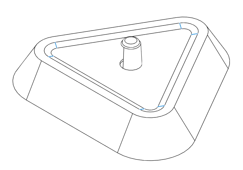
triangle_border_angle: the angle of the border extrusion.
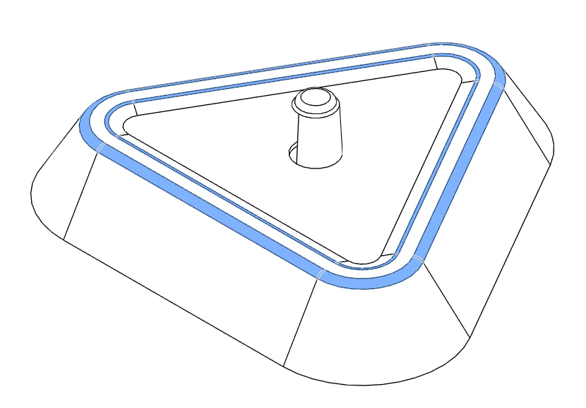
triangle_border_fillet: the redefining fillet of the upper border.
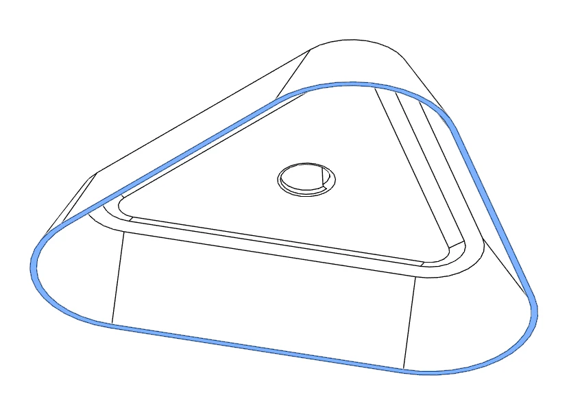
triangle_thickness: the overall thickness of the holder.
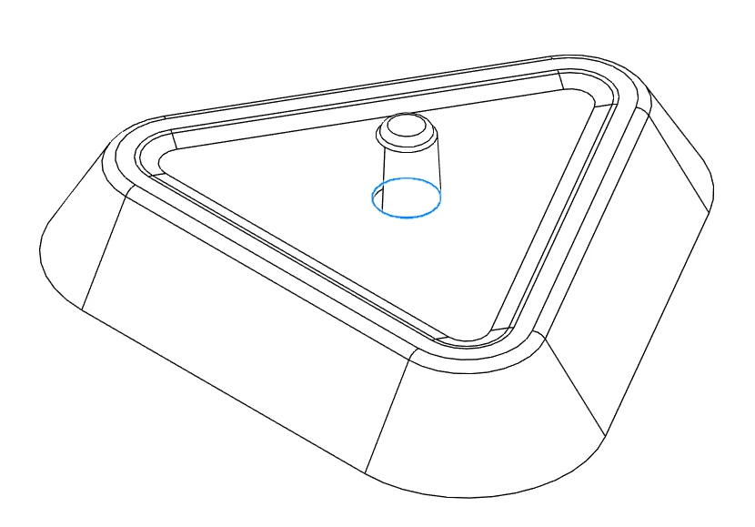
hole_diameter: the diameter of the central hole over which the pin is created.
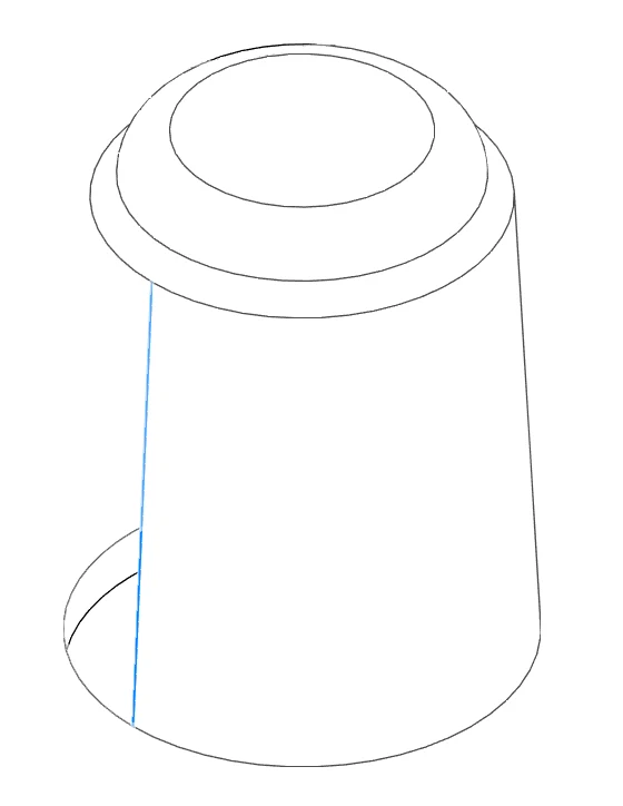
pin_height: the height of the pin, this will influence the required length of the spring.
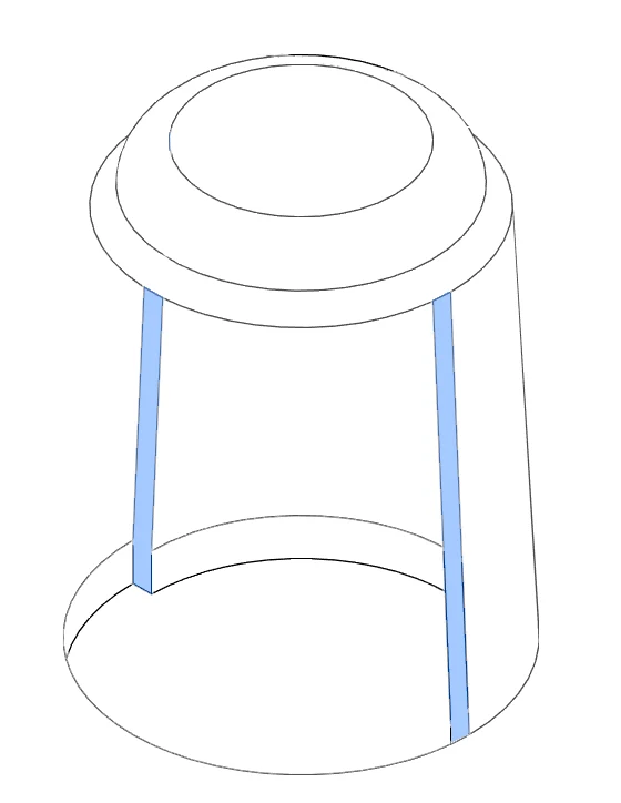
pin_wall_thickness: the thickness of the wall creating the pin.
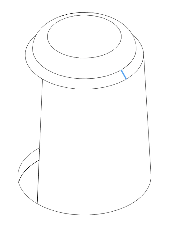
pin_cap_angle: the angle at which the pin cap is created.
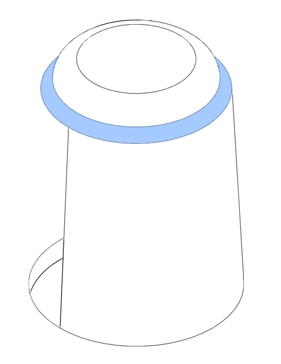
pin_cap_height_1: the height of the first part of the cap (angled)
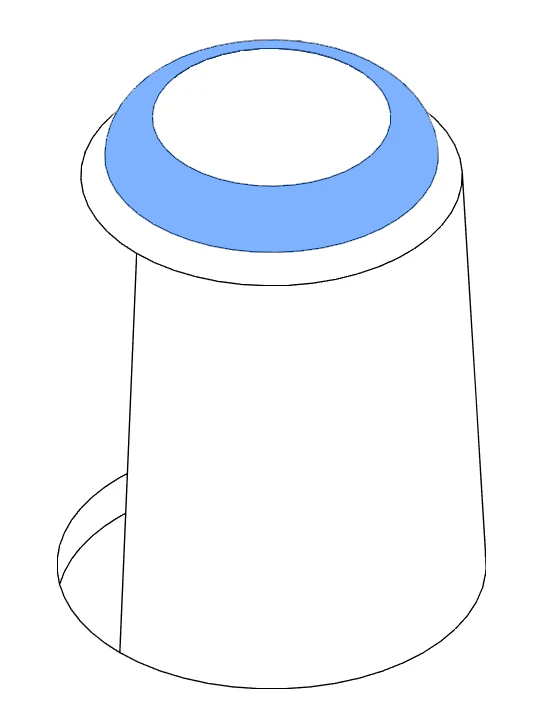
pin_cap_height_2: the height of the second part of the cap (rounded).
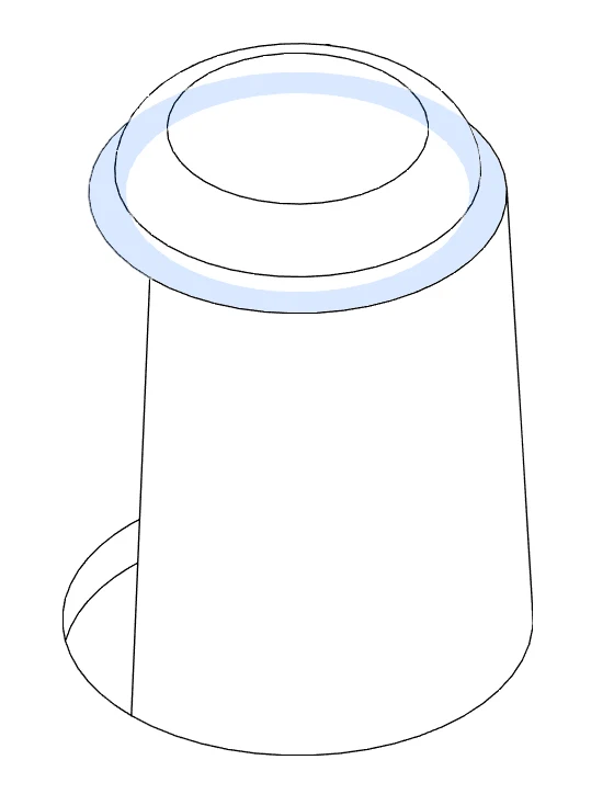
pin_cap_thickness: the width of the wall creating the cap.
Calculating the length of required spring
The minimum length of the spring can be calculated as:
(triangle_thickness + triangle_border_depth + pin_height + pin_cap_height_1 + pin_cap_height_2 - pin_cap_thickness) x 2
which with current project values is:
(1mm + 1mm + 10mm + 0.5mm + 1mm - 0.5mm) x 2
which is 26mm, hence using a 30mm spring will ensure the minimum necessary force.