Point Break Desk Toy


Point Break - Desk Toy
I am happy to share the Point Break Desk Toy, a stylish and mesmerizing addition to your office desk, or a physics toy to put anywhere in your home. Point Break visualizes rotational motion by transferring movement through interconnected mechanical components. It demonstrates the conservation of rotational motion and how energy is transmitted, making fundamental mechanics easy to observe and understand. This self resetting rotational chain reaction mechanism creates a moving wave and has been named ”Point Break” after the location where waves break when hitting land. (Originally this toy goes by the name Xylo by David C. Roy.)
The model is available in 2 different versions (”100% printed” and ”Ball bearings”) and 2 different sizes (8 pieces and 12 pieces). In my opinion, the 8 piece desk toy is a nice and reasonable print while the 12 piece is more impressive but quite large. The ”100% printed” works very well and is easier to assemble. However, it does have some wobble in the X-axis. In contrast, the ”Ball bearings” version (which requires 8 or 12 “605ZZ” or other bearings with an 14mm diameter, 5mm hole and 5mm thick), is more work to assemble but locks the rotating pieces in the X-axis and creates a much smoother, stable and satisfying movement.
Early print profiles did not include required supports. This has now been fixed. Apologies!
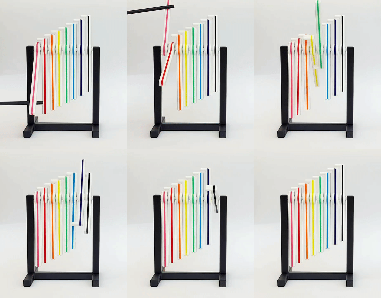
Printing
4 print profiles are available (100% printed – 8 pieces, 100% printed - 12 pieces, Ball bearings – 8 pieces, Ball bearings - 12 pieces). The print profiles include a modifier to add a second colour to the rotating bars.
There should be no issues printing the pieces needed for this model, except for the fact that the long shape of most pieces might make them prone to warping. In addition, the small ”spacers” for the ”Ball bearing” version has little contact with the bed, so overall good bed adhesion is recommended. The bar holding the rotating pieces will be under a light constant load, and I have noticed that for the large ”12 piece version”, PLA will start creeping (bending) relatively quickly while PETG seems fine. This piece should therefore be printed in another filament like PETG or ASA. The smaller ”8 piece” version seems fine in PLA (this far) but if you have other filaments available, use them. In addition, this piece needs to be perfectly printed for the mechanism or assembly to work.
Assembly
”100% printed version”
First assemble the stand by simply pressing the ”pillars” into the sockets of the ”bottom” H-shaped part (Figure 2A). This might require some force, and they should klick right into place creating a strong connection. If they for some reason are loose after pushed into place, addition of glue would probably help.
Next, line up all the ”rotational pieces as in the picture (Figure 2B), and insert the rod (Figure 2C). Next put the rod into the the stand first on one side (Figure 2D) and then on the other (Figure 2E). This requires that you slightly bend the stand apart which is fine. The only thing to keep in mind is that the orientation of the pieces as one side of the ”pillars” has an extension to keep the ”rotating bars” away from it. On the other side, the ”rotating bar” itself has this extension. For it to work properly, friction needs to be as low as possible, and for this reason adding some lubricant might be a good idea (although not required in my experience).
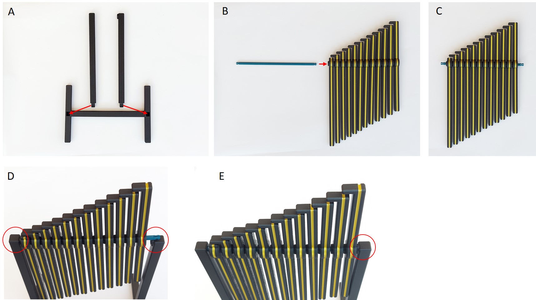 Figure 2. A) Push the long bars into the bottom stand. B) Line up all rotating rods and C) insert the Bar. D) Insert the assembly first on one side and then E) the other.
”Ball Bearing version”
The stand is first assembled as the ”100% printed version” (see above).
Push ball bearings into rotational pieces (Figure 3A-B). Next, organize the pieces as in the picture (Figure 3C), starting with one ”spacer ring” and then alternating ”rotational piece” with ”spacer ring”. The ”rod” now needs to be inserted (Figure 3D). Now, this should be difficult as we want the ball bearings to sit firmly in place on the rod. If it feels impossible, you could slightly sand the rod to make it thinner. The ”spacers” are not strictly required if the ball bearings are firmly secured on the ”rod”, but will still help creating an even distance between the ”rotational rods”.
When assembled, simply fasten the assembly into the stand (Figure 3E).
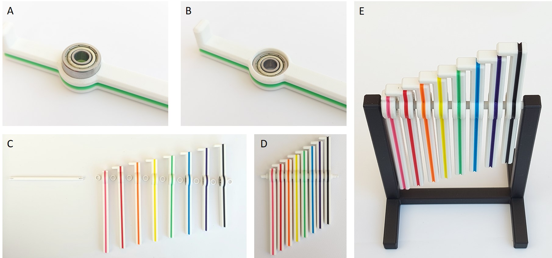 Figure 3. A-B) Insert ball bearing into slot by pressing hard. C) Line up all rotating rods and D) insert the Bar. E) Push the assembly into the stand.
You should now have an mesmerizing toy for your office desk to fidget with all day instead of doing work!
Please Enjoy!
You are prohibited from sharing, sub-licensing, selling, renting, hosting, transferring, or distributing the digital file or 3D printed versions of this object, as well as any other derivative work in either digital or physical form (including remixes).You are not allowed to use the objects in any manner that involves charging money or collecting fees without permission.