Watt Governor 瓦特离心调速器



Watt Governor Model for Demonstrating Centrifugal Force and Gear-Rod Transmission
The original device was used to regulate steam input and is a milestone in mechanical automatic control;
In the model, steam input control is replaced with a “dial” to visually show the size of the centrifugal force.
Assembled dimensions are approximately 260*90*180mm.
瓦特速度调节器模型 用于展示离心力和齿轮、连杆传动
原装置为调节蒸汽进入量,是机械自动控制的里程碑;
模型将蒸汽进入控制,改为了“表盘”,以直观展示离心力的大小
组装后尺寸约 260*90*180mm
- Simulates a double-ball centrifugal governor to demonstrate centrifugal force.
- Input via high-ratio gear transmission
- Linkage pushes the “centrifugal force gauge” for a visual display
- The two balls in the print are filled at 75% to increase weight
- Bushing design: Shaft printed horizontally, bushing printed vertically to ensure strength and improve smoothness, no extra lubrication needed
- Bushings and sliders use random seams
Chassis, bushings, and support seats use PLA. Others use PETG.
A few supports and the pointer might need glue, and the main shaft might need some sanding.
- 模拟双球离心调速器,演示离心力
- 齿轮大比例传动输入
- 连杆推动“离心力表”直观展示
- 打印配置中双球使用75%填充增加重量
- 轴套设计,轴横向打印,轴套纵向打印,保证强度同时提升光滑度,无需额外润滑
- 轴套、滑块使用随机接缝
Non-3D-printed parts required:
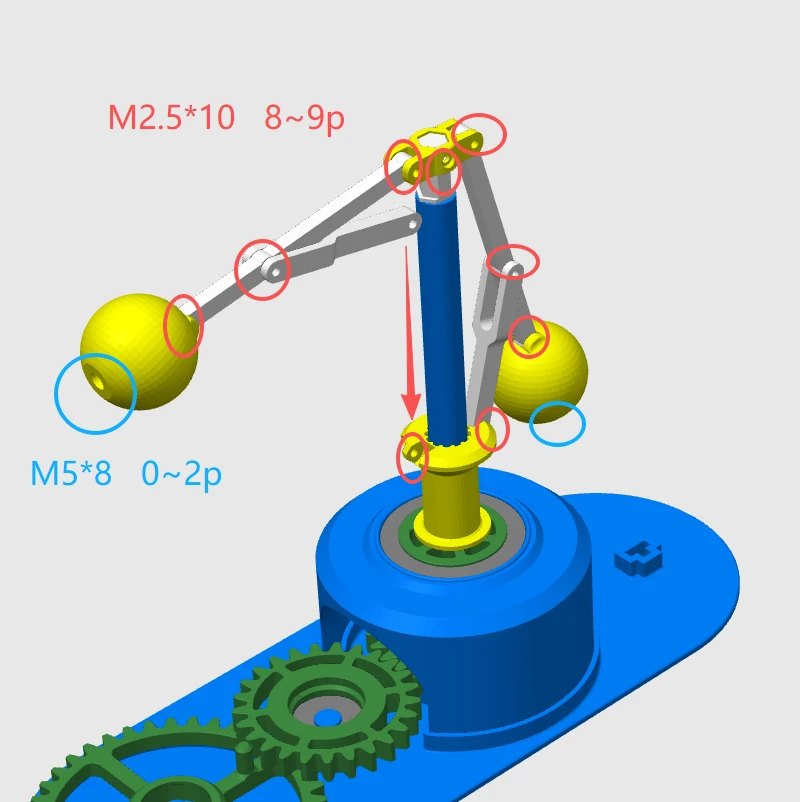
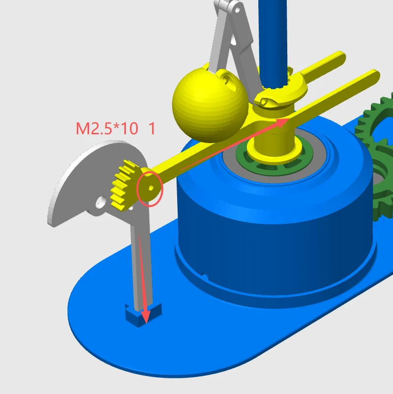
1. M2.5*10 screws, 10 pcs
2. M5*8 screws, 2 pcs (optional, used for weights)
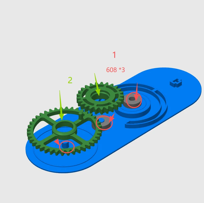
3. 608 bearings, 3 pcs
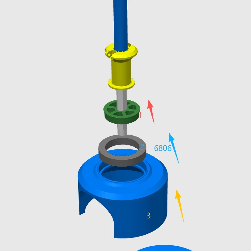
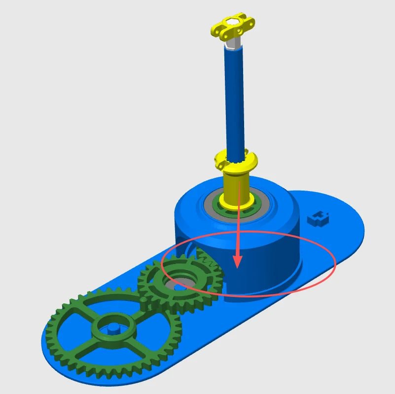
4. 6806 bearing, 1 pcs
非3D打印件需要
1、M2.5*10 螺丝 10个
2、M5*8 螺丝 2个(可选,非必须配重使用)
3、608轴承3个
4、6806轴承1个
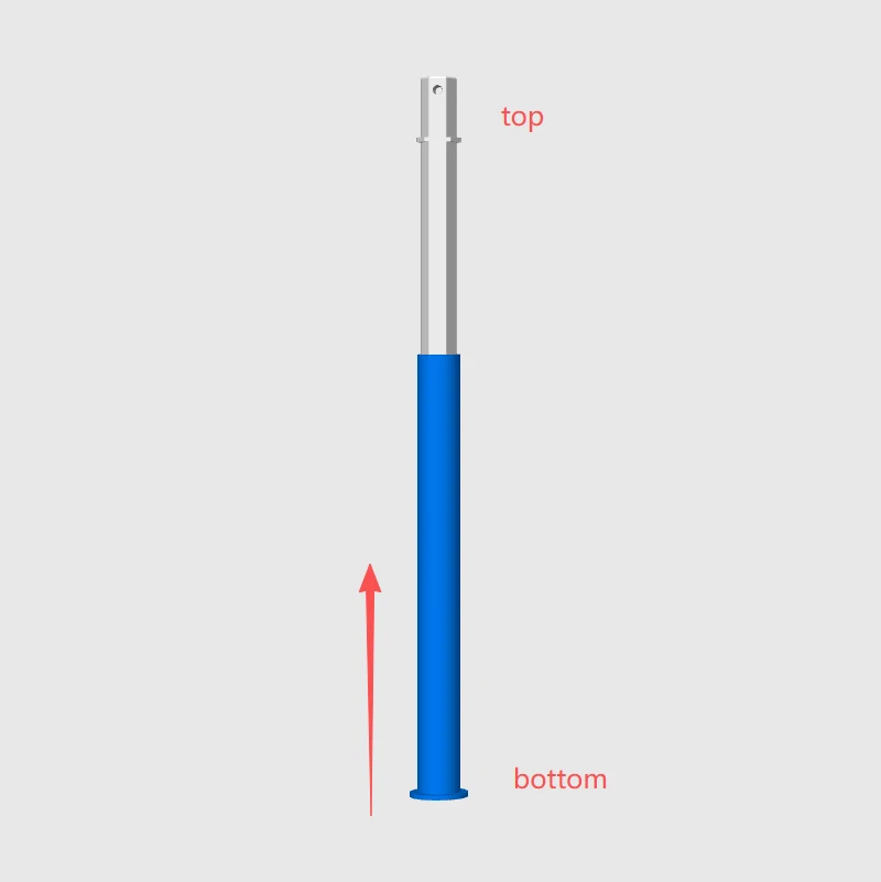
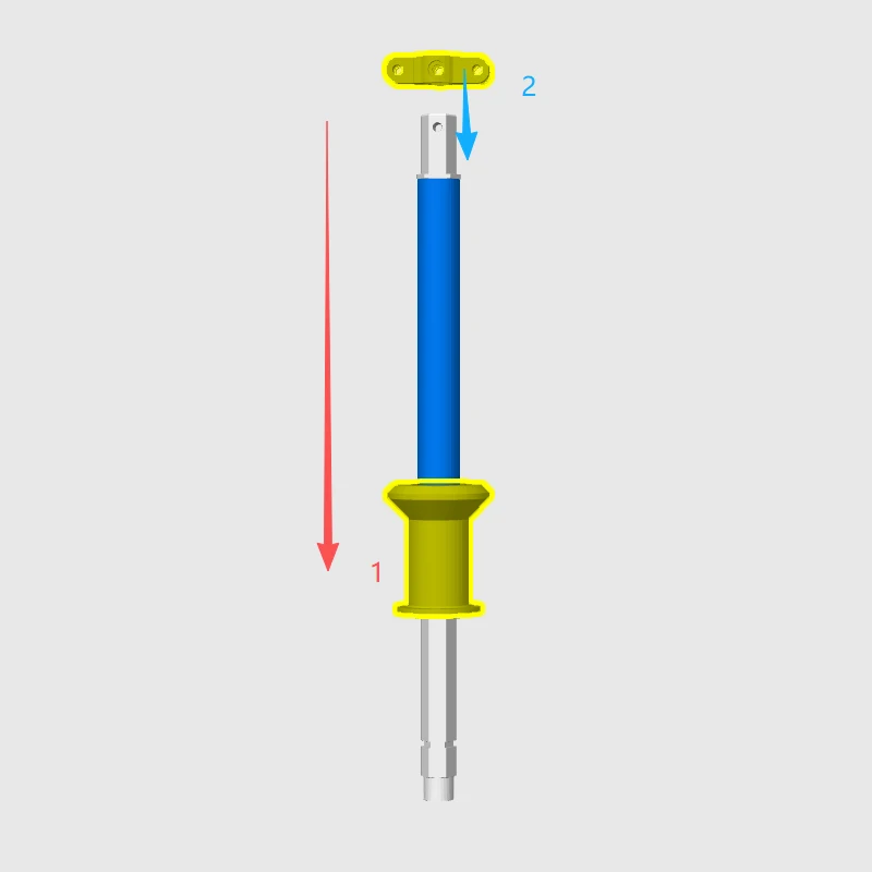
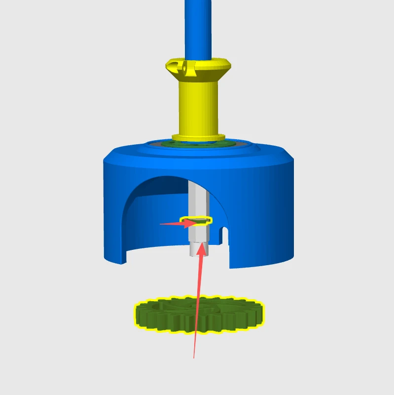
Assembly instructions:
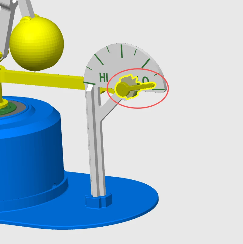
For the final step of adjusting the pointer’s direction, please adjust based on the tooth engagement of the back gear during installation.
组装示意:
最后一步指针的方向,请在安装时通过背面齿轮的咬合位置调整。